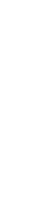

To build an electromagnet, we start with the winding of the superconducting wires. The winding is a simple operation but it takes time and requires a lot of attention. We will present the different stages to build a coil developed at the CEA for the Jefferson laboratory (United States).
In the case of this magnet, the shape of the chuck on which the niobium-titanium cable is winded has been calculated to produce a very peculiar shape of magnetic field. The turns are lined up to form regular layers. It is also necessary to constantly check the insulation of the conductor to avoid any short-circuits.
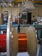
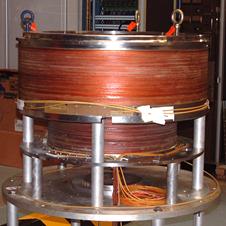
The winding device around the chuck and after 30 layers of winding, i.e. 1531 turns!
Electromagnets produce bursting forces that are proportional to the magnetic field. From the beginning of the winding operations till the end, the cable is tightened by a brake that creates a prestress so the cable will not come off the chuck under the effect of the bursting magnetic forces.
To improve the electric insulation and to fix the effect of this winding tension, each finished layer is stuck with a resin that guarantees the cohesion. However, the tension is so strong that we will have to control the conductor of the last layer and to stick the winding by a final fit. The winding of the main electromagnet, in that case, required 5786 metres of superconductor. This represents 3907 turns and 64 layers.
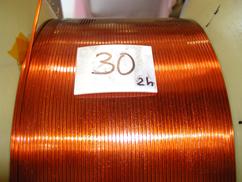
Once it has been winded, an electromagnet produces magnetic field lines that close at high enough distances for the effects of magnetism to be present way over its volume. A strong magnetic field in the centre of the winding is what we seek, but the magnetism outside the winding is often undesirable because it creates attractive forces so strong that the metal objects can be attracted even if they are several metres away. The electromagnet used in that example was designed to produce a strong vanishing field on its central axis. But for safety reason, we asked for the weakest possible outside magnetic field. The solution we used to decrease the outside field was to put another superconducting coil with opposite field around the first one. This second coil, with a bigger diameter, is designed to fold the outside field lines as close as possible to the main magnet without decreasing the field in the centre of the magnet too much.
This second coil has 579 turns and 10 layers. It required 1500 m of wire.
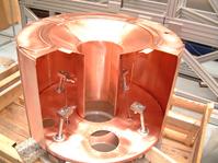
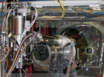
Winding of the active armour and interlocking the active winding on the coil
What makes things difficult with these electromagnets is that the niobium-titanium alloy used in the winding process is only superconducting below a very low temperature. In the most common case, as the one we are presenting, the temperature at which it becomes superconducting is -269°C (4.2 degrees above absolute zero). This is why we need to put our coil in very sophisticated thermal insulation conditions and we need a cooling device to reach such low temperatures.
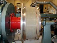
The easiest way to cool the magnet is to use liquid helium. This requires finishing the winding process in a waterproof device that will be used as a liquid helium tank.
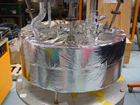
Screen cooled to -220°C and placed around the coil to avoid thermal losses. The coil is covered in a thermal super-insulating material
After that, we need to build a thermal insulation around the surrounding environment because the direct radiation between 20°C and -269°C is so substantial it would be impossible to cool. In order to do that, we put a radiation screen all over the device to intercept the outside heat. This screen is cooled by the liquid helium vapours that are collected just outside the liquid helium bath of the electromagnet. But since this is not enough to completely insulate the liquid helium bath, we add a super-insulator made of very thin layers of aluminium deposited on polyester films. With this technique, the electromagnet will only receive 0.1 watt of heat from the radiation, instead of 500 watts if we had not taken all these precautions. The rack on which the magnet is put is also cooled from 20°C to °269°C using the same method, for the same reasons. However, since the 2 coils and the mechanic parts holding them weigh a little more than 600 kg, the rack still brings an additional 0.9 watt by conduction.
To finish the insulation, we need to put the whole device in an environment that will be pumped until the vacuum is reach and there is no possibility of heat transmission through convection of the residual air, just as in a thermos bottle. Besides, all components of air are solid at -269°C. We hence do not have any other choice but to create a vacuum to insulate the different thermal parts of our device, which is no different from a cryostat.
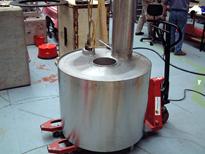
The whole device is put in a vacuum vessel
Technologically, we only have to put the electromagnet horizontally in order to add the functional parts that will be used to apply the current and the liquid helium. After that, our device will be ready to work. In order for the device to be both liquid-helium proof and vacuum proof, most of the vessels of the cryostat of the electromagnet are welded.
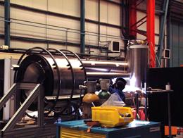
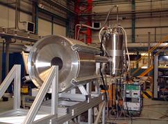
The different parts are welded. The finished magnet is put in a testing device.
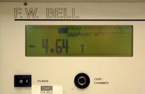
After all the usual checks, the vacuum vessel is pumped in vacuum secondary, to a pressure inferior to a millionth of a millibar, then the electromagnet is cooled with liquid helium until the nominal level of liquid helium is reached in the vessel. To finish, we slowly increase the current until we reach the nominal value of 435 A, which will give the electromagnet the magnetic field required, 4.6 teslas.
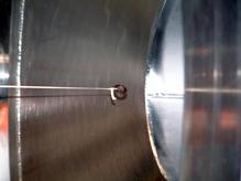
The coil works: it attracts a magnetic ring. The coil products a magnetic field of more than 4 teslas (100 000 times stronger than the earth magnetic field).
This magnet built at the CEA was delivered in 2005 and is used for physics experiments at the toroid centre CLAS at the Jefferson laboratory in Newport News, Virginia.
Characteristics of the magnet we built
Dimensions |
Inside radius |
Outside radius |
|---|---|---|
Main coil |
170 mm |
288 mm |
Armour coil |
400 mm |
418 mm |
Cryostat |
115 mm |
456 mm |